What Are You Looking For?


INTRO
Properly sizing fuses for photovoltaic (PV) systems is critical for the safe, reliable and long-term operation of this renewable power source. Unlike typical electrical power distribution and control applications, fuses in photovoltaic systems are subject to unique conditions. Prolonged exposure to elements of the environment can produce abnormal ambient temperatures, which in turn affects fuse performance, conductor selection and sizing. Also, unlike traditional circuits which are normally sized based on continuous loads, PV modules produce continuous currents,leading to additional considerations when sizing fuses. Taking these conditions into account, a unique method for sizing fuses in PV systems is necessary.
WHEN TO FUSE, WHEN NOT TO FUSE
The requirement to protect photovoltaic systems from overcurrent conditions is defined in Article 690.9(A) of the NEC. Fuses are required to protect cables and PV modules from line-line, line-ground and mismatch faults. The sole purpose is to prevent fire and safely open a faulted circuit if an overcurrent event were to occur. However, there are some situations where fusing is not required and is defined by the following:
Single Series String (fusing not required)
Two Strings in Parallel (fusing not required)
Three or More Strings in Parallel (fusing required)
Select suitable fuses for parts of the system
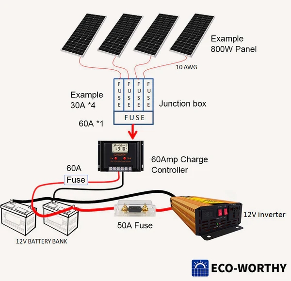
Normally, In a complete solar power system, the fuse can be added in between different components, such as from solar panel array to charge controller, controller-battery bank, battery bank-inverter.
For each part of units, the fuse requirements can be diverse, the specific ratings depends on how many amperage comes from those units and wires.
Solar Panel fusing
Normally, those solar panels over 50 watts have 10 gauge wires capable of handling up to 30 amps of current. When you have more than 3 panels connected in parallel, each capable of up to 15 amps, then a short in one panel can draw all 40-60 amps towards that short-circuited panel. This will cause the wires leading to that panel to far exceed 30 amps causing that wire-pair to potentially catch fire. In the case of panels in parallel, a 30-amp fuse is required for each panel. If your panels are smaller than 50 watts, and use only 12 gauge wires, then 20 amp fuses are required.
Parallel/Combiner Box fusing
In a parallel system a combiner box is used that holds the fuses/breakers to each panel. When sizing this “combined” fuse/breaker, we must first determine the worst case current that will flow based on our specific panels.
If we take the example 195 watt 12V panel from the introduction section, and look at the short circuit current (Isc), we see it is rated at 12.23 amps.
The National Electrical Code (NEC) also requires that a 25% factor be added if the load is continuous, so the number grows to 15.28 amps per panel. If there are 4 panels in this parallel set, then the combined current can theoretically be as high as 61.15 amps.
An 8 AWG wire set (minimum) from the combiner box to the charge controller in our example is enough, since it can handle 60 amps. A 60-amp fuse or breaker should be used in this case to protect this wire set. This also aligns with the maximum capacity of the charge controller selected.
Charge controller to Battery Fuse/Breaker
With a Pulse Width Modulated (PWN) charge controller, the worst-case amps flowing to and from the controller are the same, so the fuse and wire size can match. As an example, We recommend a 60-amp fuse/breaker for the 60A PWM charge controller, put it between the unit and the battery bank.
Battery Fuse/Breaker to Inverter
The wiring and fusing from the battery to an inverter is critical because this is where the most current will flow. Similar to the charge controller case, the recommended wire and fusing should be obtained from the inverter manual. We have already prepared a fuse holder on its positive cable, which is able to hold 50 amps current. A typical 600-watt 12V pure sign wave inverter draws up to 50 amps continuously, in that case, a cable that capable of 55-60A is required, A 6 AWG wire is what you need at least.

Monday-Friday 8:30 am-6:00 pm CST
Email : sales@eco-sources.com
Whatsapp : +8618559201506
Address : 3rd Floor, Hongye Building, Innovation and Pioneering Park, Xiamen, China